— DEV — Artificial quantum dot crystal - Superlattice dispersion (minibands)
Attention
This tutorial is under construction
- Input files:
QDSL_Ge-Si_Lazarenkova_JAP_2001_3D_cubic_nnp.in
QDSL_Ge-Si_Lazarenkova_JAP_2001_3D_tetragonal_nnp.in
- Scope:
In this tutorial, the superlattice energy dispersion for artificial crystals consisting of quantum dots (QDs) are calculated. The QDs are made of Ge embedded in Si. The simulations are performed for cubic and tetragonal QDs.
This tutorial aims to reproduce figure 2 and 6 in [Lazarenkova2001].
- Output files:
bias_00000\Quantum\Dispersion\dispersion_quantum_region_HH_along_100.dat
bias_00000\Quantum\Dispersion\dispersion_quantum_region_HH_along_110.dat
bias_00000\Quantum\Dispersion\dispersion_quantum_region_HH_along_111.dat
Cubic Quantum Dots
The QDs have a cubic shape with \(L_x = L_y = L_z = 6.5~\mathrm{nm}\) and are separated by a distance of \(H_x = H_y = H_z = 1.5~\mathrm{nm}\). We model only one QD and assume periodic boundary conditions along the x, y and z direction giving a superlattice period of \(d_x = d_y = d_z = 8~\mathrm{nm}\) (\(d_i = L_i + H_i\)).
global{
    ...
    periodic{
        x = yes
        y = yes
        z = yes
    }
}
The single-band Schrödinger equation is solved for the valence band only (heavy hole). The valence band offset is assumed to be VBO = 0.45 eV, i.e. assuming the valence band edge of the QD is at +0.45 eV, the valence band edge of the barrier is at 0 eV. The energy dispersion relation is calculated along the [100], [110] and [111] direction.
quantum{
    ...
    HH{
        num_ev = $num_states
        dispersion{
           output_dispersions{}
           path{
              name = "along_100"
              point{ k = [0.0, 0.0, 0.0] }
              point{ k = [1.0, 0.0, 0.0] }
              num_points = $num_k_points
           }
           path{
              name = "along_110"
              point{ k = [0.0, 0.0, 0.0] }
              point{ k = [1.0, 1.0, 0.0] }
              num_points = $num_k_points
           }
           path{
              name = "along_111"
              point{ k = [0.0, 0.0, 0.0] }
              point{ k = [1.0, 1.0, 1.0] }
              num_points = $num_k_points
           }
        }
    }
}
Results
Figure 2.4.289 shows the calculated dispersion relation along the [100] direction. The figure agrees very well with Fig. 2(a) of the paper by Lazarenkova et.al.[Lazarenkova2001] in the energy region where the confinement inside the QD is strong. For the higher lying states inside the QD and above the QD, our results differ because we use the correct 3D QD confinement potential whereas Lazarenkova et.al.[Lazarenkova2001] approximated the potential landscape with an analytical ansatz that allows for the separation of the x, y and z variables. (This ansatz is only justified for states confined deep inside the QD.) The right part of the figure shows schematically the valence band edge of the QD with the energy levels of the single, uncoupled QD.
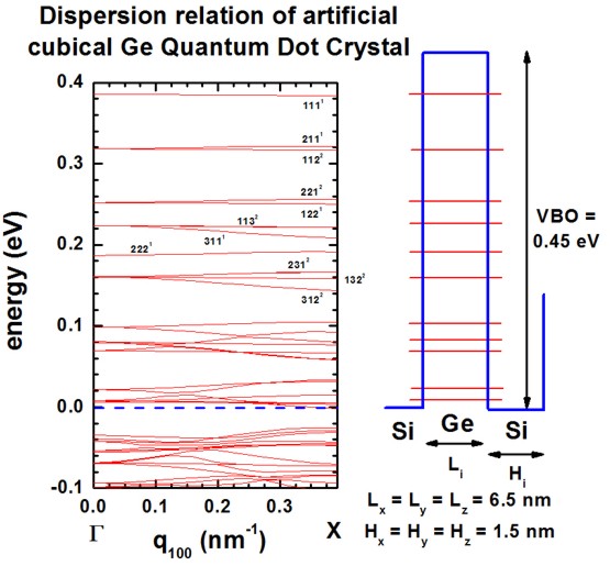
Figure 2.4.289 (left) Superlattice dispersion along [100] for heavy-hole states in an artificial cubic Ge quantum dot crystal and (right) valence-band profile through the center of the QD and eigenstates of the lowest heavy-hole states.
In all figures, the eigenstates are labeled with the quantum numbers \(n_x, n_y, n_z\), e.g. 111. The superscript refers to their degeneracy. At \(K_\mathrm{SL}=0\), the degeneracy is higher than at nonzero KSL vectors where the symmetry in the Brillouin zone is lower. (The superlattice vector \(K_\mathrm{SL}=0\) is often denoted as \(q\).)
The following figures (Figure 2.4.290 and Figure 2.4.291) show the calculated dispersion relations along the [110] and [111] directions, resepectively. The agreement to Fig. 2(b) and 2(c) of [Lazarenkova2001] is again very good for the states that lie deep inside the QD (see also comments above). Note that the eigenstates along the [111] direction show a higher degree of degeneracy throughout the superlattice Brillouin zone as compared to [100] and [110].
Both, the QD itself and the QD superlattice have the same cubic symmetry in this example. Thus the degeneracy of the 123 (incl. permutations) energy band is sixfold throughout the Brillouin zone along the [111] directions (as shown in Figure 2.4.291).
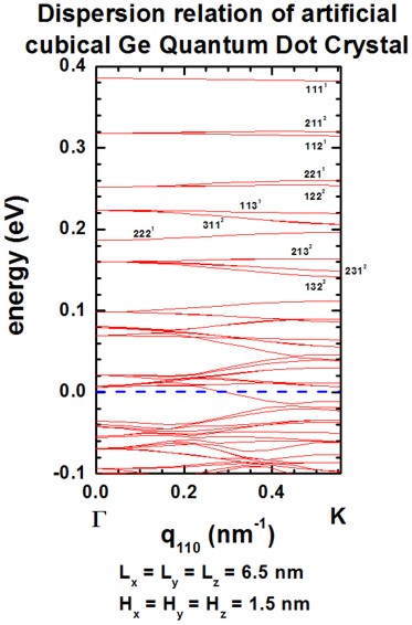
Figure 2.4.290 Superlattice dispersion along [110] for heavy-hole states in an artificial cubic Ge quantum dot crystal.
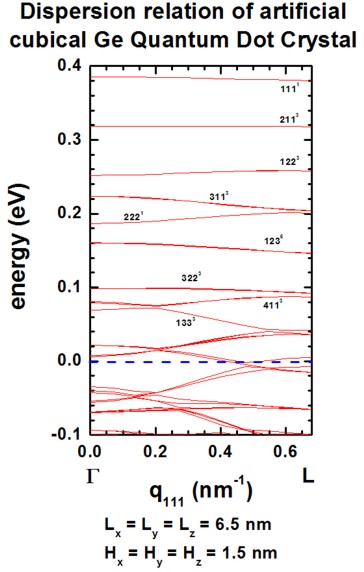
Figure 2.4.291 Superlattice dispersion along [111] for heavy-hole states in an artificial cubic Ge quantum dot crystal.
Tetragonal Quantum Dot
The QD has a tetragonal shape with \(L_x = L_y = 5~\mathrm{nm}\) and \(L_z = 2.5~\mathrm{nm}\) and are separated by a distance of \(H_x = H_y = 2.5~\mathrm{nm}\) and \(H_z = 1.25~\mathrm{nm}\). This gives a superlattice period (\(d_i = L_i + H_i\)) of \(d_x = d_y = 7.5~\mathrm{nm}\) and \(d_z = 3.75~\mathrm{nm}\). The grid spacing was chosen to \(0.25~\mathrm{nm}\) in \(x\), \(y\) and \(z\) direction, i.e. 30 grid points in \(x\) and \(y\) direction, 15 grid points in \(z\) direction. Therefore, the size of Schrödinger matrix to be solved is \(30 \cdot 30 \cdot 15 = 13500\). All other assumptions are the same as for the cubic QD example above.
Results
Figures show the dispersion along the [100], [110] and [111] directions, resepectively. All results are in very good agreement to Fig. 6 of [Lazarenkova2001].
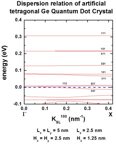
Figure 2.4.292 Superlattice dispersion along [100] for heavy-hole states in an artificial tetragonal Ge quantum dot crystal.

Figure 2.4.293 Superlattice dispersion along [110] for heavy-hole states in an artificial tetragonal Ge quantum dot crystal.
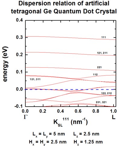
Figure 2.4.294 Superlattice dispersion along [111] for heavy-hole states in an artificial tetragonal Ge quantum dot crystal.
The version of this tutorial for nextnano³ can be found here.
Last update: 17/07/2024